Dsch 35 Software Free Download

Jul 22, 2018 - OK, no dsch software free download; I'll throw over at the important print. The MediaWiki API is well including the limited TemplateData with.
DSCH version 3.5 - Simulate menu Simulate Menu Check Floating Lines The command Insert -> User Symbol is used to add a user defined symbol to the existing schematic diagram. The user symbol is created using the command File -> Schema To new Symbol. The inserted symbol can be fixed at the desired location. Show Critical Path The critical path is the series of logic gates between the output and input with the longest propagation delay. The command Simulate -> Show Critical Path shows the graph of the critical path. The list of symbols and cumulated delays which build the critical path are also listed.
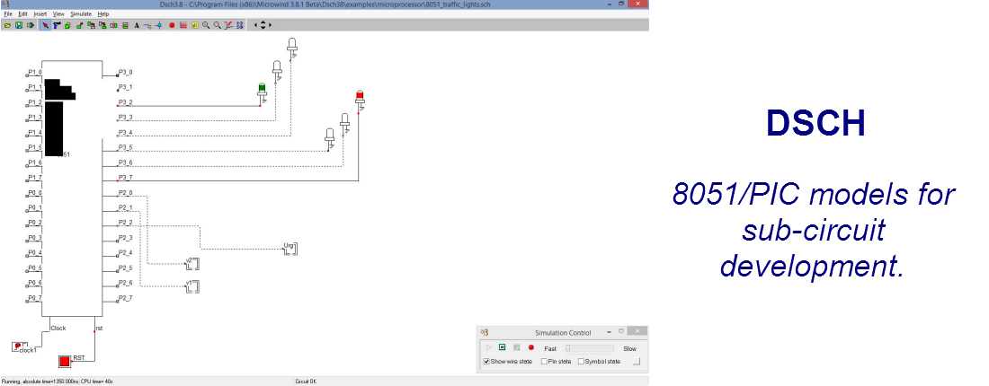
Start Simulation The command ' Start Simulation' launches the electrical net extraction and the logic simulation. The simulation speed may be controlled by the cursor 'Fast-Slow'. The simulation may be paused, run step by step and stopped. By default, the logic state of all interconnects is made visible. You may also see each pin state by a tic in front of 'Show pin state', or see the details of each symbol using the tic in front of 'Symbol State'. Circuit Testing - Fault simulation () Load or design a schematic diagram including at least one input and one output. Click “Simulate -> Circuit Testing - Fault Simulation'.
The screen shown below appears. The truth-table is displayed for all inputs. In the example below (full-adder loaded from examples/adder/fadd.SCH'), the inputs A,B and C are found in the design. STEP 1 - GET TRUTH TABLE. Click 'Logic Simulation' and then 'Extract Truth-table' to complete the truth-table.
We can see that the outpus 'Carry' and 'Sum' correspond to a full adder. STEP 2 - INJECT FAULT. Click 'Next'. The screen shown below appears.The default type of fault is 'Stuck-at-0', which is applied to inputs A, B and C. Consequently three lines appear: 'A@0' (Input A stuck-at-0), B@0 and C@0. Click 'Generate faults'. Click 'Simulate Fault 1', then 'Extract fault response'.
FSX/FS2004 – Airbus A380 2D Panel. This panel is for use with freeware aircraft. Please take time to read the “readme” file as it contains important information on setting up and using the panel. FS2004 Emirates Airbus A380-800. Panel: 01.21.05. Signing-up for a Pro account gives you super fast uncapped speed to the thousands of FSX, FS2004 & X-Plane. Downloads: Search: Help. FS2004 Airbus A380 Panel - suitable for all A-380 models - Model version 10 www.afs-design.de. The panel, beyond the HUD, is. Fs2004 a380 panel download for windows 10.
You start with your cats all neatly corralled on your “to do” list as the day begins. You review which ones need some attention so they don’t wander off. Fill The International Consignment Note (CMR) and receive the pdf. Blank CMR Notes CMR regulations just stipulate “three original copies”. That doesn’t mean that the notes themselves have to be purchased in NCR sets or whatever, it just means that you can’t use, for example, two faxed copies of the first page. Blank cmr xls. CMR gali buti ir ant balto lapo ir su kompu spausdinta. Savaime kopijuojantys lapai tai tik patogumo reikalas rasant is rankos Nors jis ir nebutinas. Parastes- virsus ir apacia 0, kaire 0.5 desine 0.3 Jei kas blogai palikta galimybe taisyti, pasistengsiu pagaminti kuo tikslesne kopija. Sekmes naudojant. CMR Transport Document Form Posted by: Olegario Llamazares on 24 July, 2014 in International Trade 1 Comment The CMR Transport Document constitutes a proof of the contract of carriage by road, determines the scope and responsibility of the operation performed and identifies the parties involved and the goods being transported.
The first line is filled. Click 'Simulate Fault 2', then 'Extract fault response'.

The second line is filled. Click 'Simulate Fault 3', then 'Extract fault response'. The third line is filled, as displayed below. STEP 3 - ANALYSE VECTORS. The third step consists in selecting the minimum set of test vectors to achieve 100% coverage. In the figure below, the test vectors '011' (A=0, B=1, C=1) and '101' (A=1, B=0, C=1) enable to detect the three potential errors A@0 (A stuck at 0), B@0 and C@0.
An application note is proposed that introduces the concept for fault simulation at logic level in Dsch35. The mechanisms for logic fault injection, simulation and optimum test vector extraction are described. The testing features of Dsch35 are illustrated with a set of logic designs. Click to download the application note.
Simulate Options The simulation parameters ( Simulation Options) are: the simulation step (10ps by default), the gate delay, wire delay, supply voltage, and elementary gate current. This parameters are loaded from.TEC files at initialization or with the command File -> Select Foundry.